
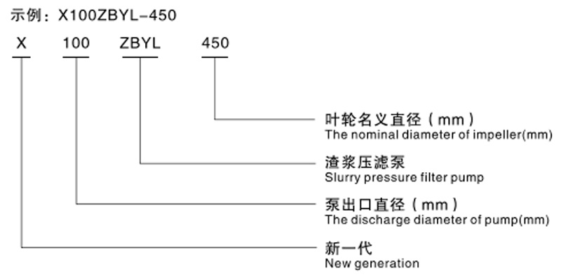
XZBYL Series Slurry Filter Press Pump
Category:
Product Details
1. Changes in flow and head of the filter press feed pump during the filtration process
Stage 1: Start feeding stage. Since there is no pressure inside the filter press chamber, the process requires the slurry to quickly fill the chamber. At this time, the pump should operate at high flow and low head.
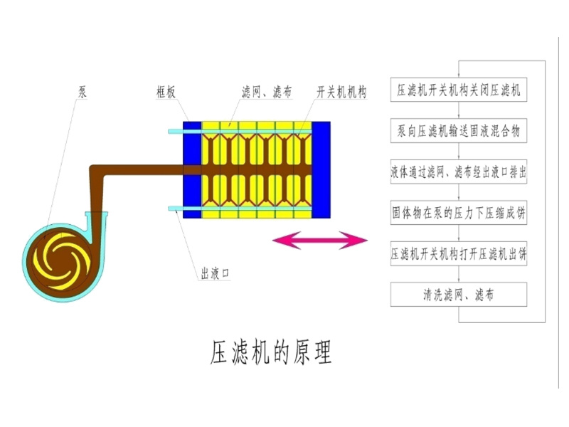
Stage 2: Filling stage. As the solids gradually fill the filter press chamber, the internal pressure increases, and the outlet flow gradually decreases; the pump flow should gradually decrease while the head gradually increases.
Stage 3: Cake pressing stage. The outlet flow of the filter press approaches zero, high pressure is required, the pump flow should also approach zero, and the pump head is at its highest. The solids are compressed into a cake after being held under pressure for a period.
2. Fluid analysis inside the pump when using a conventional slurry pump as a filter press feed pump
Feeding and filling stages
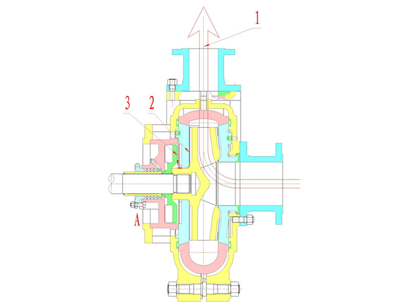
The vast majority of slurry enters the filter press along line 1, while a small portion attempts to flow along line 2 under pressure. However, due to the pressure reduction effect of the impeller blades and auxiliary impeller, a pressure f is generated along line 3, preventing slurry from flowing toward line 2. Therefore, with reasonable design, leakage at packing A is minimal.
Pressure holding stage
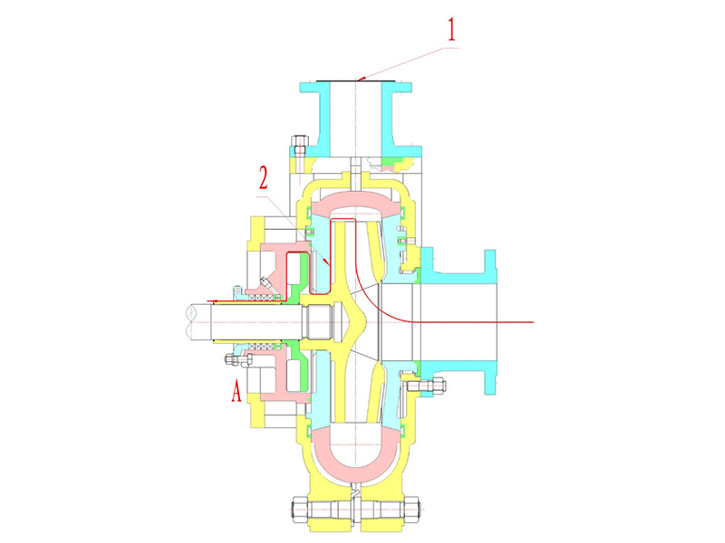
Pump flow is zero, pump head is highest, and internal pump pressure is maximum, equivalent to being closed at outlet 1. With no outlet path, slurry can only flow along line 2, causing significant leakage at packing A. Since the third stage requires compressing solids into a cake, it takes a long time. Leakage causes heavy pollution; meanwhile, pump efficiency drops sharply.
This is why we need to develop a slurry filter press pump.
3. Innovative structure of the slurry filter press pump
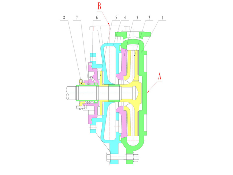
1. Pump body 2. Impeller 3. Pump cover 4. Suction section 5. Auxiliary impeller 6. Pressure reduction cover 7. Packing 8. Packing gland
Structurally, the biggest innovation of the slurry filter press pump is relocating the suction port from point A to point B and sealing the original pump suction port.
4. No-leakage principle of the slurry filter press pump
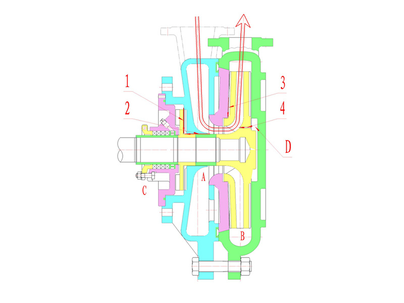
Since the suction port is relocated between the pressure reduction cover, pump body, and pump cover, regardless of the filtration stage or changes in pump flow and chamber pressure, the pressure in chamber A at the suction port remains constant and equal to the inlet pressure. Packing C communicates with the suction port (same pressure). We know the inlet pressure is generally a few meters of water head, so by reasonably designing a small auxiliary impeller, packing seal C can be guaranteed leak-free.
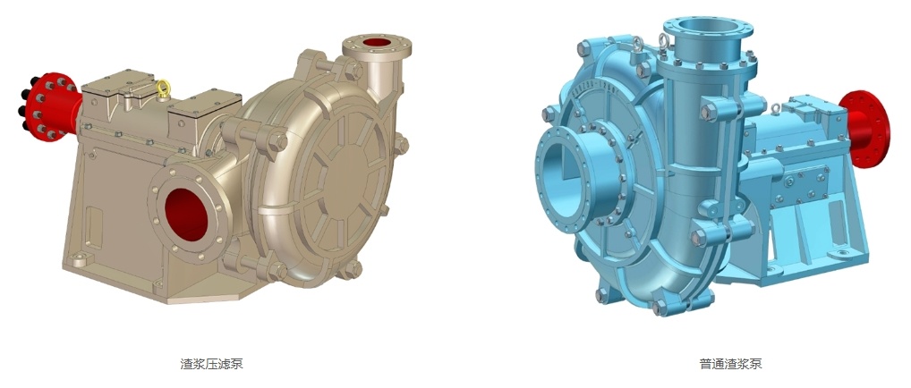
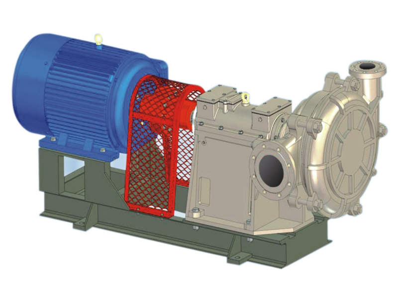
Innovative structure (appearance)
X Summary of features of the ZBYL series slurry filter press pump
a. Completely solves the leakage problem of filter press feed pumps.
b. The pump design applies the "no overload design" theory: low head at high flow, high head at low flow. After selecting appropriate motor power, the pump can operate without motor overload across the full flow range.
c. Performance curves fully meet the filter press pump requirements.
4. Pump efficiency fully meets the premium grade requirements of "JB/T53060-93 Centrifugal Slurry Pump Product Quality Classification".
5. The application of reliability technology combined with the above features greatly extends the pump's service life compared to ordinary slurry pumps.
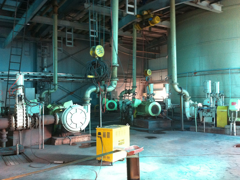
Field application of slurry filter press pumps
The pump uses radial suction combined with auxiliary impeller sealing technology to completely solve the leakage problem of filter press pumps.
Using pump CAD technology and optimization theory design, the pump efficiency is high. The series pumps all meet the premium grade requirements of "JB/T53060-93 Centrifugal Slurry Pump Product Quality Classification".
The pump design applies the "no overload design" theory. The head curve with low head at high flow and high head at low flow fully meets the slurry pump requirements during filter press slurry filtration. After selecting an appropriate motor, the pump can operate without motor overload across the full flow range.
The ZBYL series slurry filter press pumps can replace ordinary slurry pumps and traditional two-stage filter press pumps in coal, steel, mining, and other industries.
The XZBYL series slurry filter press pump is an improved version of the ZBYL series slurry filter press pump:
1. The pump's suction end, pressure reduction cover, and auxiliary impeller are changed from ordinary cast iron to wear-resistant materials, greatly improving the service life of these parts.
2. From the pump body perspective, the suction port layout is improved from only the left side to both left and right sides of the pump body, providing users with options.
3. Incorporating user feedback on the ZBYL pump, the XZBYL improves strength and reliability, further extending the service life of the whole machine and main components.
4. The new generation XZBYL filter press pump has lower head at high flow, better meeting the slurry pump requirements during filter press slurry filtration.
5. The series pump varieties increased from 4 to 6, adding x100ZBYL-450 and x150ZBYL-630 models; the design flow range increased from 14 m³/h to 468 m³/h, meeting all global filter press slurry pump requirements.
Trivia
1. Generally, the required pressure for slurry filter presses is 6-7 kgf/dm³. Excessive pressure can damage the filter cloth; too low pressure results in insufficient cake dryness.
2. The working pressure of the filter press equals the clean water head of the slurry filter press pump multiplied by slurry density and the head ratio coefficient.
That is: P=0.0098×Hm×ym
=0.009×H×Hr×ym ( KPa )
P=Hm×Sm/10=H×Sm×Hr/10 ( kgf/cm )
ym: Slurry density (kg/m )
Hm: Pump slurry head (m)
Sm: Slurry weight
H: Clear water head converted from slurry head (m)
Hr Head ratio (the ratio of the head when pumping slurry to the head when pumping clear water under the same flow and speed)
3. When calculating the outlet pressure of the cyclone, the slurry head needs to be changed to the outlet slurry (the total slurry head of the pump and all negative forces of the slurry transported by the pump) for head calculation.
Keywords:
XZBYL Series Slurry Filter Press Pump
Honors and Qualifications


Recommended Products
Inquiry
If you have any questions, please contact us immediately and we will respond as soon as possible
VIEW MORE ⇀You can also follow us on social media
Email Subscription
©2024 Hubei Tianmen Huanai Pump Co., Ltd.